Terminal No. (Symbol) | Wiring Color | Terminal Description | Condition | Specified Condition |
|---|
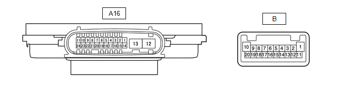
A16-11 (TNS) - Body ground | W - Body ground | Left turn signal light signal input | Ignition switch ON, left turn signal light off | Below 1 V |
Ignition switch ON, left turn signal light blinking | 11 to 14 V ←→ Below 1 V | | | |
A16-16 (SBR) - A16-15 (SGR) | B - BE | Rear height control sensor sub-assembly LH power supply | Ignition switch ON | 4.75 to 5.25 V |
A16-17 (SHRL) - A16-15 (SGR) | W - BE | Rear height control sensor sub-assembly LH signal input | Ignition switch ON, vehicle unloaded, vehicle stopped | Approximately 2.5 V
(value decreases as the front of the vehicle is raised) |
A16-20 (LINL) - Body ground | P - Body ground | LIN communication line | Ignition switch off | Below 1 V |
Ignition switch ON | Pulse generation | | | |
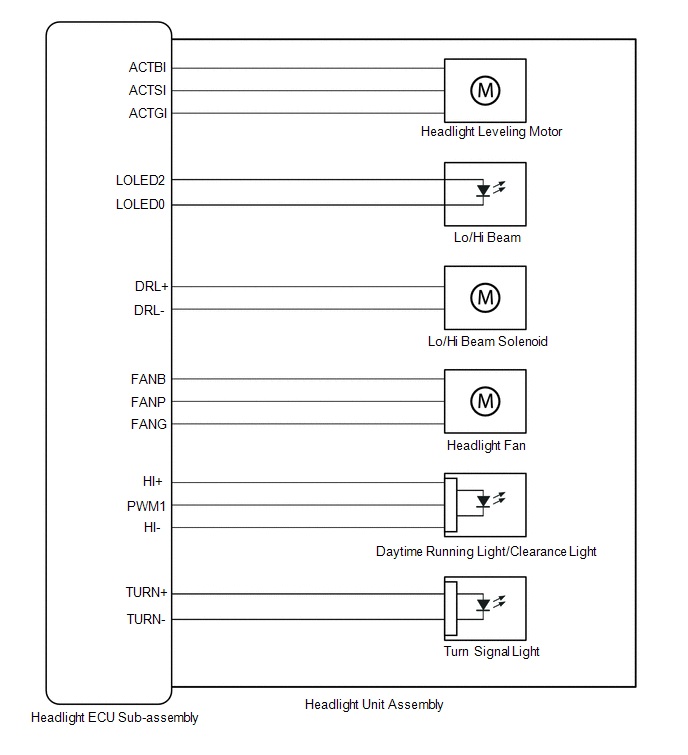
B-20 (DRL+) - B-11 (DRL-) | - | High beam headlights drive output | High beam headlights off | Below 1 V |
High beam headlights on | 11 to 14 V | | | |
B-4 (LOLED2) - B-3 (LOLED0) | - | Low beam headlights/high beam headlights drive output | Low beam headlights and high beam headlights off | Below 1 V |
Low beam headlights or high beam headlights on | 11.2 to 17.7 V | | | |
B-7 (ACTBI) - B-17 (ACTGI) | - | Headlight leveling motor power source | Ignition switch off | Below 1 V |
Ignition switch ON | 11 to 14 V | | | |
B-8 (ACTSI) - B-17 (ACTGI) | - | Headlight leveling motor signal output | Ignition switch ON, low beam headlights on, vehicle height not changed | Below 1 V |
Ignition switch ON, low beam headlights on, vehicle height changed and maintained for more than 3 seconds | 1.0 to 14 V | | | |
B-9 (TURN+) - B-13 (TURN-) | - | Left turn signal light signal output | Ignition switch ON, left turn signal light off | Below 1 V |
Ignition switch ON, left turn signal light blinking | 11 to 14 V ←→ Below 1 V | | | |
B-16 (PWM1) - B-1 (HI-) | - | Daytime running lights/clearance lights control signal output | Daytime running lights and clearance lights off | Below 1 V |
Daytime running lights or clearance lights on | Pulse generation | | | |
B-10 (HI+) - B-1 (HI-) | - | Daytime running lights/clearance lights power source | Daytime running lights and clearance lights off | Below 1 V |
Daytime running lights or clearance lights on | 11 to 14 V | | | |


.png)
.png)
.png)